DIN rail power supply units: How the service lifetime is determined by the temperature
As a system engineer, it is important to have a reliable and long-lasting power supply on which you can rely. Failure of the unit after a short time is annoying, costly and time consuming.
Heat is the archenemy to long service life and reliability:
The minimum lifetime of power supplies is determined by the lifetime of the electrolytic capacitors. The warmer it is, the faster the electrolytic capacitors dry out. Even a temperature rise of +10 °C in the power supply cuts in half their service lifetime. In order to achieve the longest possible service lifetime for DIN rail power supplies, it is essential that the device is protected against overheating. The cooling concept in the power supply is an important factor for this. Ideally, the power supply is built in a way that prevents the unit from generating heat at all. In practice, however, the ideal case is not possible due to the power losses.
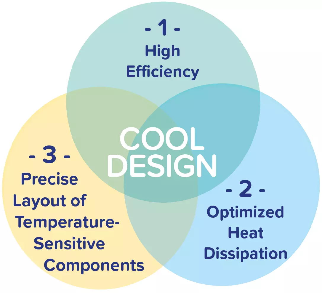
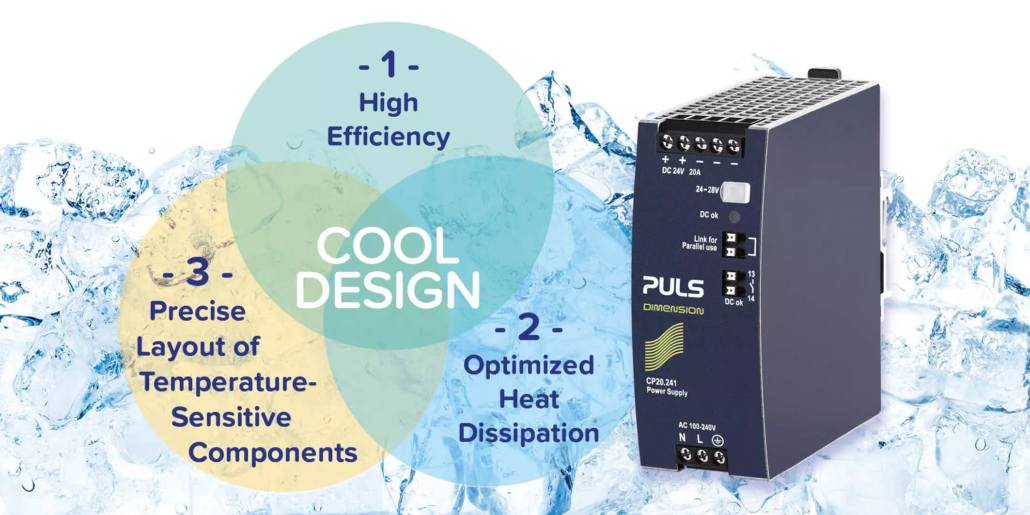
Graphic 1: Cool Design = High Efficiency + Optimized Heat Dissipation + Precise Layout of Temperature-Sensitive Components
The PULS Cool design ensures a long service lifetime
To ensure a long service lifetime of power supplies, the heat generation in the devices must be kept to a minimum. PULS defines “Cool Design” as the interaction of three essential points that lead to low heat generation: Firstly, the consistently high efficiency, secondly, the optimized dissipation of heat losses to the surroundings of the device, and thirdly, the well planned arrangement of temperature-sensitive components in the unit.

Higher efficiency means less heat
An essential factor for low heat generation in the power supply is, a high efficiency of the unit.
The efficiency value describes the ratio of output power to input power of a power supply. The difference is converted into heat as loss. The advantage of high efficiency is obvious on closer examination. The lower energy losses mean that not much heat is generated in the first place, thus reducing the amount of cooling required. As a result, the electrolytic capacitors achieve the service lifetime specified by the manufacturer. The reliability of the entire unit is also increased (see graphic 2).
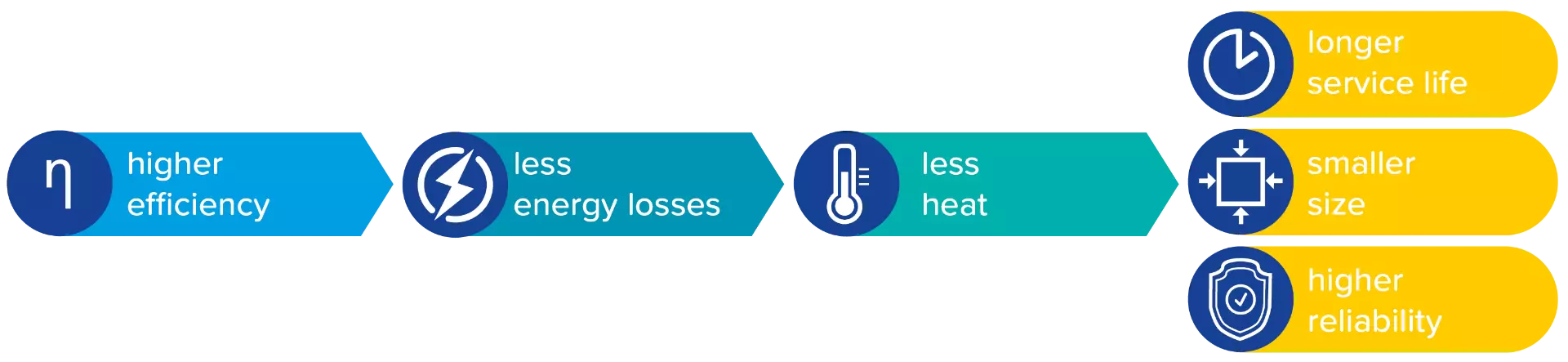
Graphic 2: A high efficiency leads to less energy loss in the form of heat. This is reflected in a longer service lifetime of the power supply units, a smaller design and higher reliability.
High full-load efficiencies make a small designs possible. Due to the lower heat generation in the unit, heat sinks can be partially omitted (see graphic 2). However, partial load efficiencies are also becoming increasingly important in practice. Usually, power supplies are not operated permanently under full load. For the thermal design of control cabinets, therefore, the losses of the typical load must be taken into account (see graph 3 for the example CP20.241).
The losses during no-load operation must also be taken into account. These should also be low so that they do not cause thermal stress in the control cabinet even in “standby mode”.
The rule is: The higher the efficiency, the lower the power loss of a power supply in the form of heat.
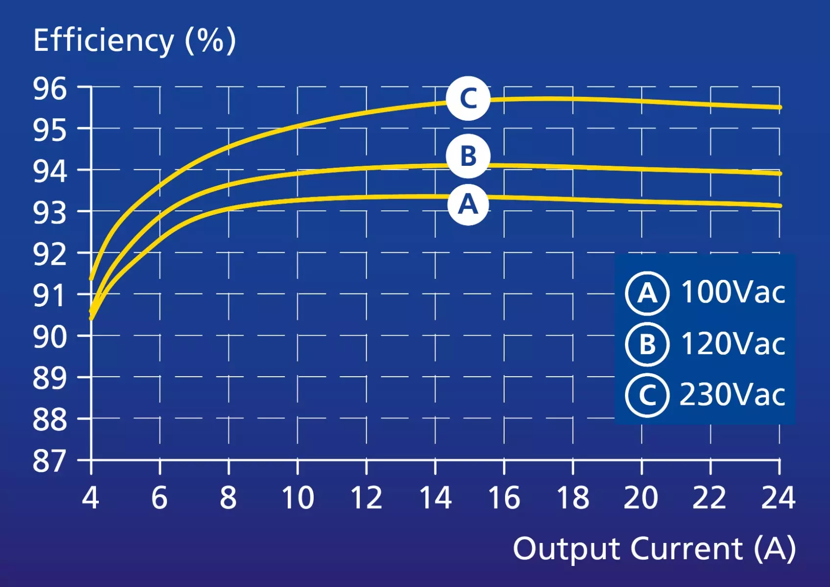 Graphic 3: High efficiencies not only at full load, but across a wide load range (example CP20.241)
Optimized heat dissipation is essential for a long service lifetime
Heat puts a strain on the service lifetime of components. In addition to high efficiency, another factor for a long service lifetime is a good cooling concept.
Despite high efficiency, a small amount of energy is always lost. PULS units have a very high efficiency of up to 95.6 %. The remaining 4.4 % of the input power is lost. The heat generated by the losses is unavoidable and must be dissipated directly to the surroundings. The outer surfaces of the housing and the convection air flow that passes through the unit serve this purpose. The convection air flow should be able to flow without obstruction between the components.
In practice, however, this is difficult to achieve. Power supplies are becoming increasingly complex and smaller at the same time. Space inside the device is limited. This makes it even more important to install cooling ducts and consider them equal to the other components in the device. In addition to the installed cooling ducts, short and direct connections of the heat generators are also an option in order to keep as little heat as possible in the device. A smart cooling concept often eliminates the need for internal heat sinks. This benefits the low weight and also significantly reduces the cost of the power supply.
The right component arrangement is the key
The optimal arrangement of temperature-sensitive components is essential for long lifetime of units.
Circuit designers tend to optimize the arrangement of components according to electrical requirements. In doing so, they often compromise on thermal design. In order to ensure the longest possible service lifetime, life-determining components must be placed in the cooler areas. Temperature-sensitive components are primarily electrolytic capacitors, varistors and optocouplers. The electrolytic capacitors can be placed near the cool air flow.
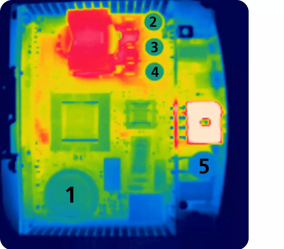
Graphic 4: Thermographic image
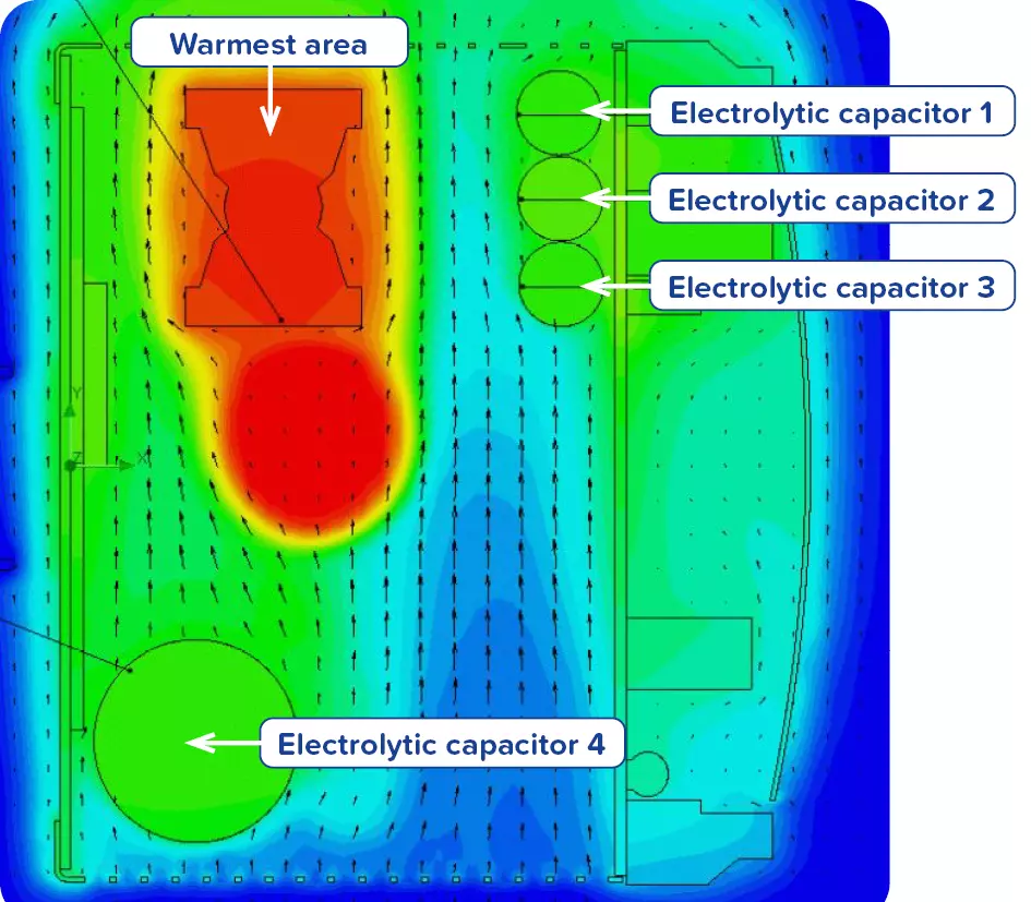
Graphic 5: Thermographic image
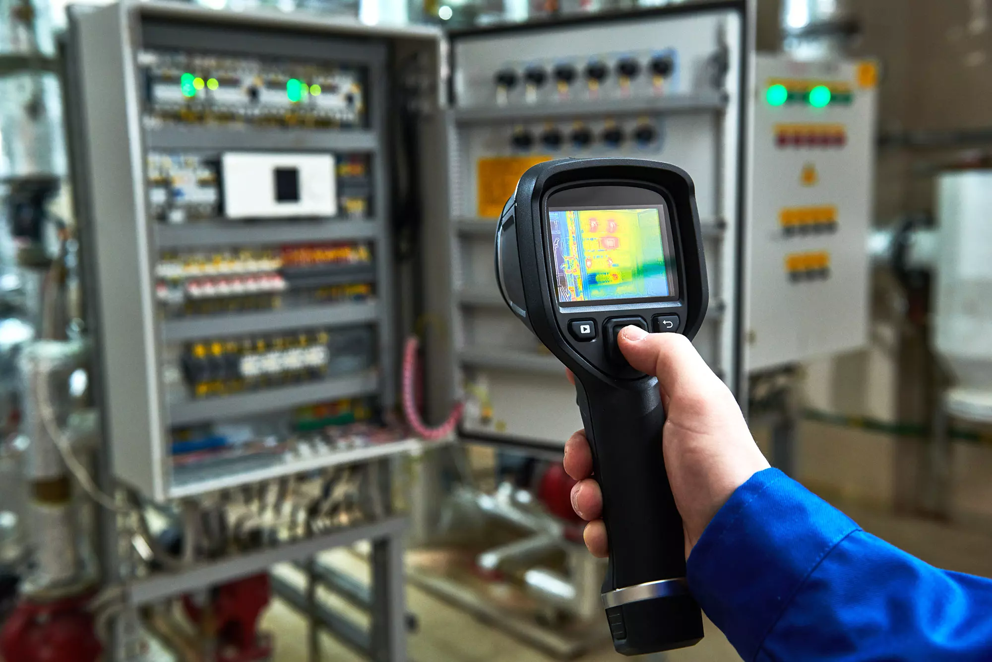
The practical test: A unit under a thermal imaging camera
Thermography can be used to prove that these measures contribute to a cool power supply. Thermography makes it possible to look inside DIN-rail power supplies. They are especially informative in the case of convection-cooled switched mode power supplies.
The practical test with a high-tech thermal imaging camera shows the hot spots in the device. the heat development in certain areas and the position of the components that heat up the most. Due to the “Cool Design”, the unit can develop its full potential under load without overheating.
In convection cooling, the warm air is directed outwards by a flow. The effect of a functioning air flow can be proven by thermography.
The shown thermographic image of a PULS CP10 clearly demonstrates that sensitive components, such as the electrolytic capacitors (image labels: 1, 2, 3, 4, 5), have been optimally placed and stay cool (see graph 4 + 5).
 What is the meaning of the IP ratings for power supplie...25. August 2023
 DC-UPS modules – with battery or capacitor?7. April 2022