Power supplies with IO-Link port
Real-time information on power, temperature and status data is supplied directly from your power supply via IO-Link.
Integrated IO-Link port
Power supplies ready for communication
The power supply is placed at a central nodal point in the system. There is more than just current flowing. A power supply records a significant amount of real-time information that is of particular interest to the operating firm as well as the system manufacturer.
This data can help increase system availability and reduce maintenance and operating costs. This means the power supply has the potential – in parallel with its function as a converter – to also act as a sensor and therefore make a significant contribution to the Industrial Internet of Things (IIoT).
PULS offers a variety of DIN rail power supplies and field power supplies with IO-Link interface.
Power and data
Reliable power and IO-Link feature
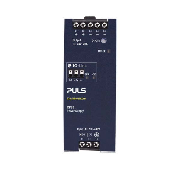
480 W
DIN rail power supply
1-phase | 24 V, 20 A
95.5 % efficiency and 48 mm width
+ 20 % BonusPower (up to +45 °C)
60 A for up to 12 ms
Active PFC (harmonic correction)
Full power between -25 °C and +60 °C
Order number: CP20.242-IOL


Networking function
IO-Link v1.1 (IEC 61131-9)
Push-in terminals
Transmission speed: COM 3 (230.4 kBaud)
Integrated non-volatile memory
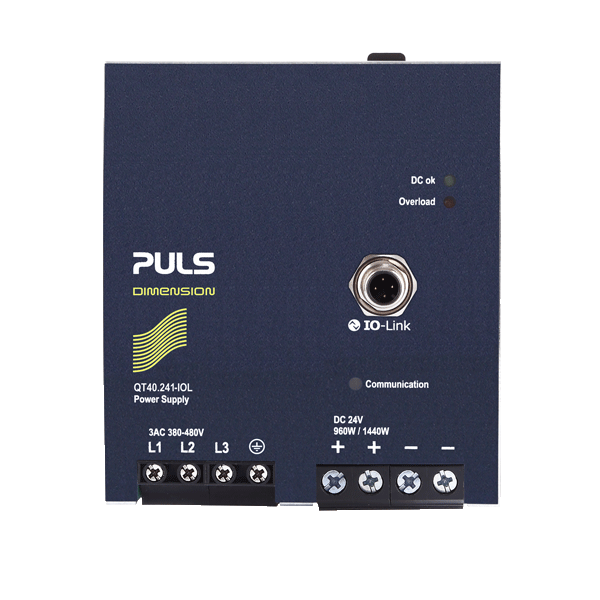
960 W
DIN rail power supply
3-phase | 24 V, 40 A
95.3 % efficiency and 110 mm width
+ 50 % BonusPower for 5 s
100 A for 10 ms to trip circuit breakers
Active PFC (harmonic correction)
Full power between -25 °C and +55 °C
Order number: QT40.241-IOL


Networking function
IO-Link v1.1 (IEC 61131-9)
4-pole M12 plug connector
Transmission speed: COM 3
(230.4 kBaud)
Integrated non-volatile memory
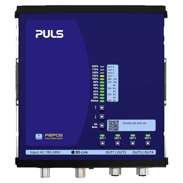
360 W
Field power supply
1-phase | 24 V, 15 A
95.7 % efficiency and 181 mm width
+ 50 % BonusPower for 5 s
IP65 and IP67
4 switchable outputs
Outputs for actors and sensors separately protected
Active PFC (harmonic correction)
Full power between -25 °C and +55 °C
Order number: FPS300.245-034-105
Further 360 W and 600 W FIEPOS devices with IO-Link are available here.


Networking function
IO-Link v1.1 (IEC 61131-9)
M12-A male plug connector
Transmission speed: COM 3
(230.4 kBaud)
Integrated non-volatile memory
New
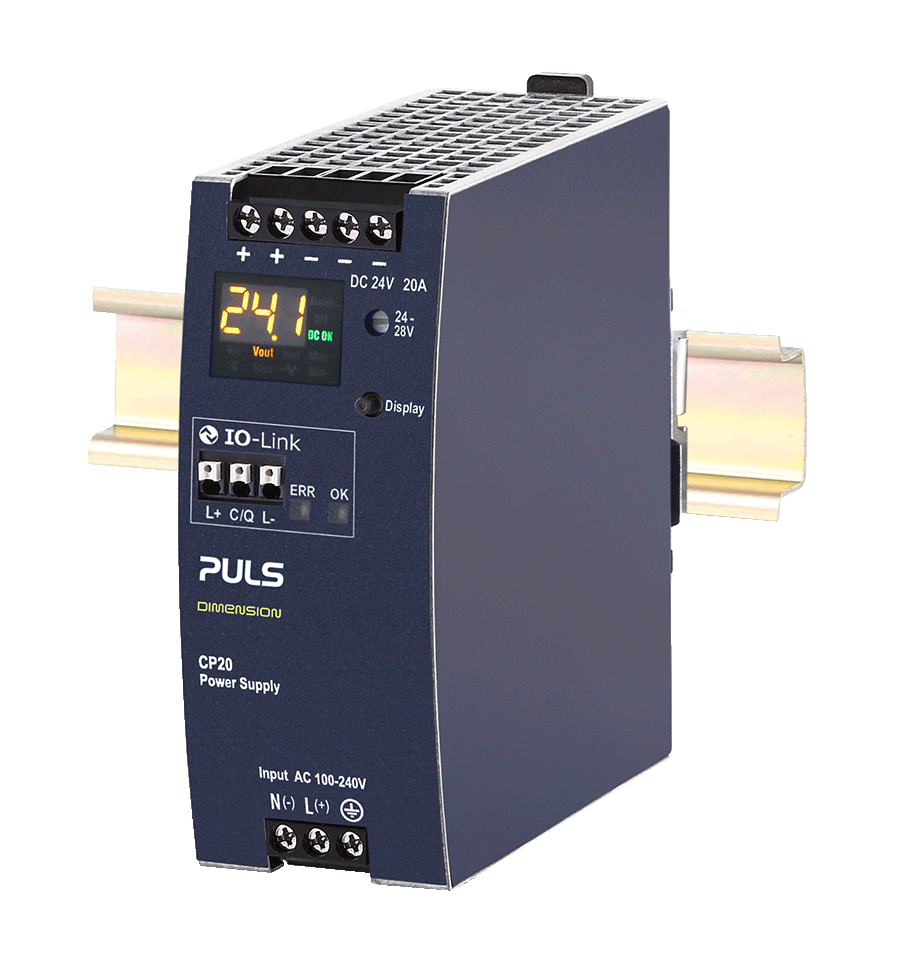
480 W
DIN rail power supply
1-phase | 24 V, 20 A
Integrated IO-Link interface and Power Supply Condition Display (PSCD)
Order number: CP20.248-IOL

Award-winning IO-Link device
– even before market launch
The Manufacturing Leadership Council of consulting firm Frost & Sullivan looks for innovations that contribute to digitalisation in the production industry.
With that in mind, PULS submitted the QT40.241-B2 to the panel in the first quarter of 2018. The panel members conducted intensive tests to examine the added value that the power supply offers production companies and were impressed by the user-oriented strategy of PULS.
The result was the QT40.241-B2 being awarded the respected Manufacturing Leadership Award even before its official market launch.


Valuable information
Data from your application


Device information (static)
- Manufacturer name
- Product name
- Serial number
- User specific marking
- Hardware and firmware inspection status


Device information (dynamic)
- Stress level
- Remaining lifetime
- Internal temperature
- Total operating hours
- Turn-on counter
- Uptime


Input parameters | RECORDED
- Transient counter
- Input voltage (Vrms)


Output parameters | REALTIME
- Output current (A)
Output parameters | RECORDED
- Output voltage (V)


Events | PUSH
- DC-OK
- DC warning
- BonusPower
- Temperature too high (capacitors)
- Temperature too high (airflow)
- Overload
- High voltage on input
- Low voltage on input
- Power supply down
- Predictive maintenance recommended
- 2-phase operation (for 3-phase devices only)
- Humidity too high


Remote functions | WRITE
- Switch on power supply
- Switch off power supply
- Set output voltage
Communication protocol
Advantages of IO-Link
Reliable
The component requirements for an IO-Link port in the power supply are relatively low when compared to more complex communication protocols.
This offers several advantages: thanks to the low number of additional components, the MTBF value (Mean Time Between Failures) of the QT40.241-IOL remains constantly high.
The MTBF stands at 622,000 hours (MTBF SN 29500 at 3AC 480 V, 24 V, 40 A, +40 °C) and is indicative of the reliability and thus the fault tolerance of the device.
User-friendly
IO-Link was designed as a user-friendly plug-and-play solution. Installation and operation are easily and cost-effectively implemented.
The port can be cabled using standard, unshielded IO cables. In addition, compatibility with all standard fieldbus and automation systems is provided, ensuring flexible usage options.
Safe
IO-Link is very robust and also offers a high level of safety. Industrial power supplies are often exposed to the harsh environments of the lower automation level and also need to be protected against external manipulation.
Data transmission via IO-Link has been field-tested for these applications.
Enhancing existing IO-Link systems
Seamless power supply integration
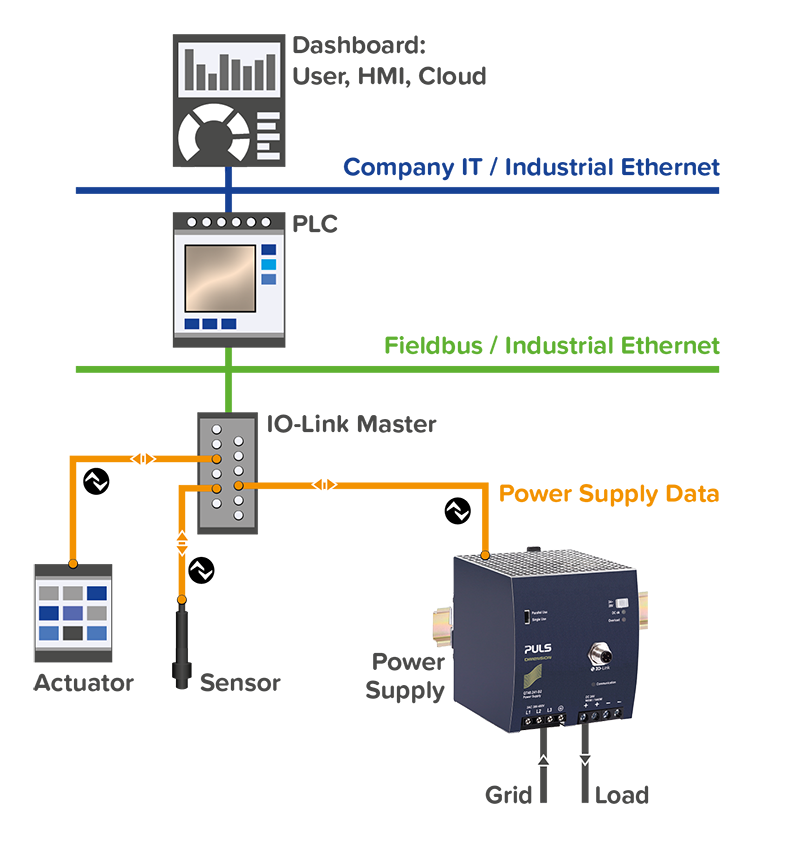
IO-Link was designed to retrieve the signals of the sensors and actuators (IO-Link devices) from the field level. Via an IO-Link master, these are fed into the respective fieldbus system and transmitted to the automation system.
The combination of fieldbus and IO-Link thus enables continuous communication across all levels. IO-Link is an open standard that is compatible with all common fieldbus and automation systems. This allows flexible use.
The integration of the into an existing IO-Link system requires only a connection to the IO-Link master. For this purpose, standardized, unshielded IO cables are used. The installation and operation are thus uncomplicated and can be implemented cost-effectively.

At a glance
Your benefits
Save
time and cost
- Demand-oriented, preventative maintenance
- Automated parameterisation when replacing units
- Avoid downtime
- Improved system capacity utilisation
Improve
customer service
- Rapid analysis and troubleshooting in the event of a fault
- Quality analysis of the power grid
Facilitate
machine learning
- Automatic detection of wear via digital load profiles
- Avoid big data problems (incompatibility, inconsistency, etc.) with current as the data source
Consult with power supply experts
Personalised support
Contact our product experts today for personalised technical support and advice on selecting the optimal power supply solution.
We are committed to contributing to your business success with our innovative and reliable products. Reach out to our product experts and find the best solution for your application today.


